 Manufacturing Toolkit

Drawings in the Manufacturing Toolkit data model represent 2D design documents. These documents may be associated with 3D models or exist independently, especially if created by 2D CAD software. A drawing typically consists of one or more sheets, showing the design from different views to capture all essential details in a 2D form.
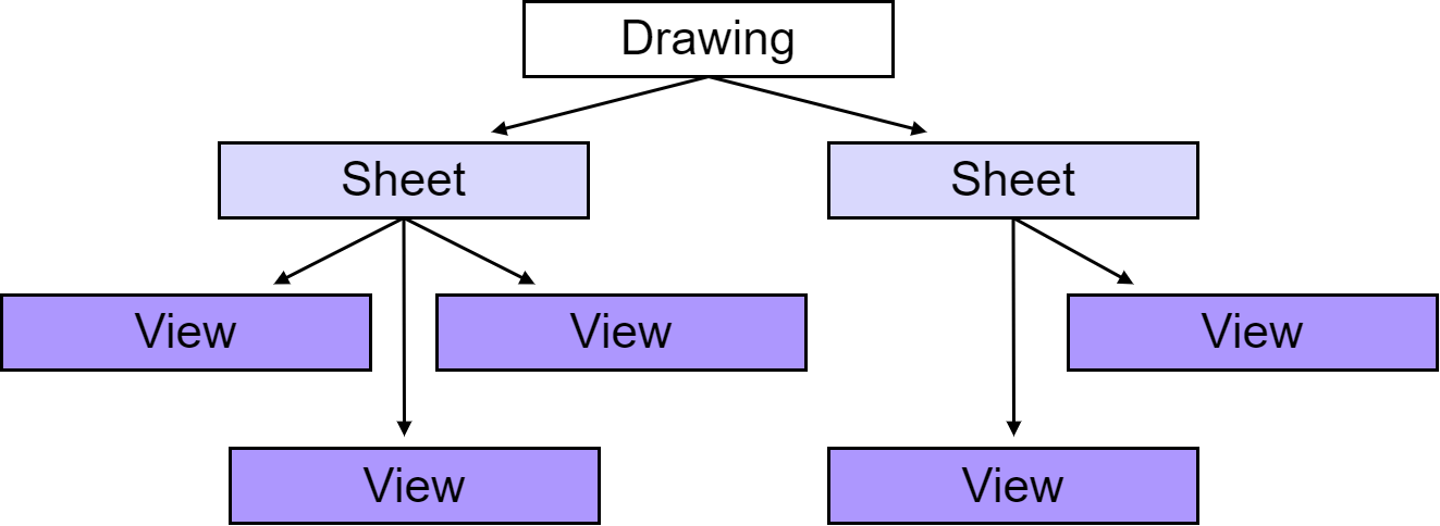
Drawing::Drawing is the primary class responsible for encapsulating all information related to a model drawing. If the imported model includes drawing data, this will be stored as Drawing::Drawing in the ModelData::Model class. The drawing structure is composed of two main elements: sheets and views. The diagram below shows a possible drawing structure:
Here's how the original example from this article could be mapped into this structure:

Sheets represent the physical sheets of paper used in real-world drawings. Each sheet has a defined size and orientation. Since one sheet may not be sufficient to capture all the details of a 3D model, a drawing often includes multiple sheets, each containing several model views. In the Manufacturing Toolkit, this concept is represented by the Drawing::Sheet class.
A view provides a visual representation of the model from a certain angle or side. In engineering practice, there are several specific types of views, such as cut views, broken views, and detail views. However, the Manufacturing Toolkit does not distinguish between these types. Instead, Drawing::View class serves as a container for the 2D geometry required to represent the model from a given angle.
Layers are logical groups of drawing elements, and each element belongs to only one layer. Layers help organize objects in a drawing, based on their function or purpose. Layers provide control over properties such as visibility, line type, and color for all objects in them. Drawing::Layer class is used for layers in drawings.
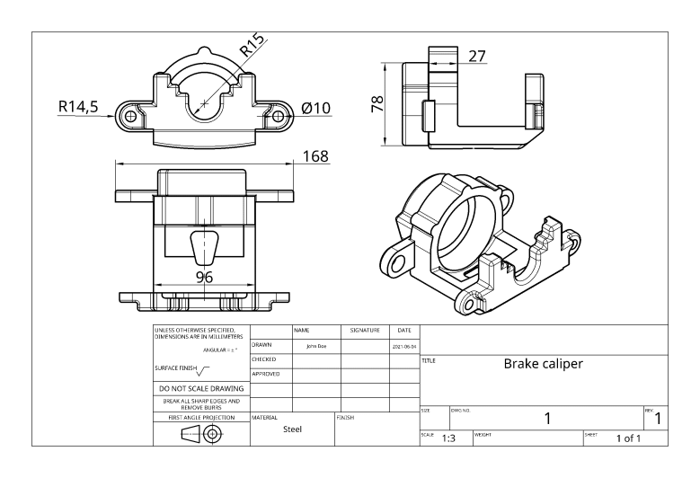
The example drawing at the top of the page is composed of a single sheet with 4 views (3 side views and 1 isometric view).
The actual content of drawings consists of 2D geometry, stored in instances of Drawing::View . Drawings in the Manufacturing Toolkit can represent 2D geometry in various forms, including curves (Drawing::CurveSet ), piecewise contours (Drawing::PiecewiseContour ), and points (Drawing::PointSet ). These geometric representations are complementary, allowing a single view to contain elements of different types to completely describe its geometry.
In addition to model geometry, drawings can include dimensions (Drawing::Dimension ), hatches (Drawing::Hatch ), and text blocks (Drawing::Text ). There are several types of dimensions available; please refer to the documentation for the classes derived from Drawing::Dimension to learn how these types are defined.
Generally, drawings also include other types of data, most notably various annotations such as notes, multileaders, tables, and etc. These are currently not supported by Manufacturing Toolkit drawings but may be added in the future.
The drawing structure is fixed, featuring only two levels of nesting. To facilitate traversal of child entities within the structure, SheetIterator and ViewIterator are provided. A general strategy for using these iterators is illustrated below:
Once you have an instance of the Drawing::View class, its contents can be accessed using either an iterator or a visitor. The ElementIterator can be used when all elements need to be processed uniformly, regardless of their specific type, or when you need to retrieve an element at a specific position. Below is an example of how to use an iterator:
The Drawing::ElementVisitor is suitable for cases where the type of the drawing element is important, or when only specific types need to be processed. Additionally, the Drawing::ElementVoidVisitor
is provided to simplify the implementation for derived classes in such scenarios. Below is an example of how to use it to count only the 2D analytical curves in a view: