 Manufacturing Toolkit

Demonstrates how to perform machining design analysis on a 3D model and print information about found issues and their parameters in a console.
This example demonstrates how to perform machining design analysis on a 3D model using machining DFM analyzer tool (DFMMachining_Analyzer). For this purpose, used a console application that imports a STEP model, traverses through unique ModelData_Part , creates and runs DFMMachining_Analyzer, groups and prints information about found issues and their parameters into console. Machining design analysis will be performed for each unique ModelData_Part , but only for the scope of accepted geometries.
Application needs 2 input arguments to run:
For more information about machining design analysis visit CNC Machining Design for Manufacturing (DFM) page.
PartProcessor class is inherited from SolidProcessor and overrides ProcessSolid method that are used to run design analysis on given shape. To reduce computation time, Machining_Data will be used as an input argument to perform design analysis. Machining data contains information about found features, therefore, the first step is to run Machining_FeatureRecognizer. The Machining_FeatureRecognizerParameters.SetOperation() method of the tool parameters is used to set the type of operation (Milling or LatheMilling). The operation type will be taking into account during recognition process and the recognition result will be different depending on it.
Once feature recognition is done, design analysis is run for various sub-processes (drilling / milling / turning). CombineFeatureLists method is used to combine issues from design analysis of different sub-processes.
After design analysis is performed, PrintIssues method is used to print information about found features and their parameters in a console.
Visit Model Explore Helper Implementation page for more information about base SolidProcessor class implementation.
To traverse only unique parts of the imported model, the ModelData_ModelElementUniqueVisitor class is used.
After performing design analysis, the object of FeatureGroupManager class is used to group and sort found issues. For this purpose, there is a traverse through all found issues and add each of them to FeatureGroupManager with a specified name.
After adding all found issues to FeatureGroupManager, a Print method of the manager is used to print information about found issues and their parameters in a console. PrintFeatureParameters is created to explore and print issue parameters. It uses as an input parameter of Print method.
Visit Feature Group Helper Implementation page for more information about FeatureGroupManager class implementation.
The first is an example output for model from ./examples/models/Fresamento_CAM1_v3.stp and operation set to Milling. and the second one is an output for model from ./examples/models/senthi.step and operation set to Lathe+Milling.
| Model | Example output |
|---|---|
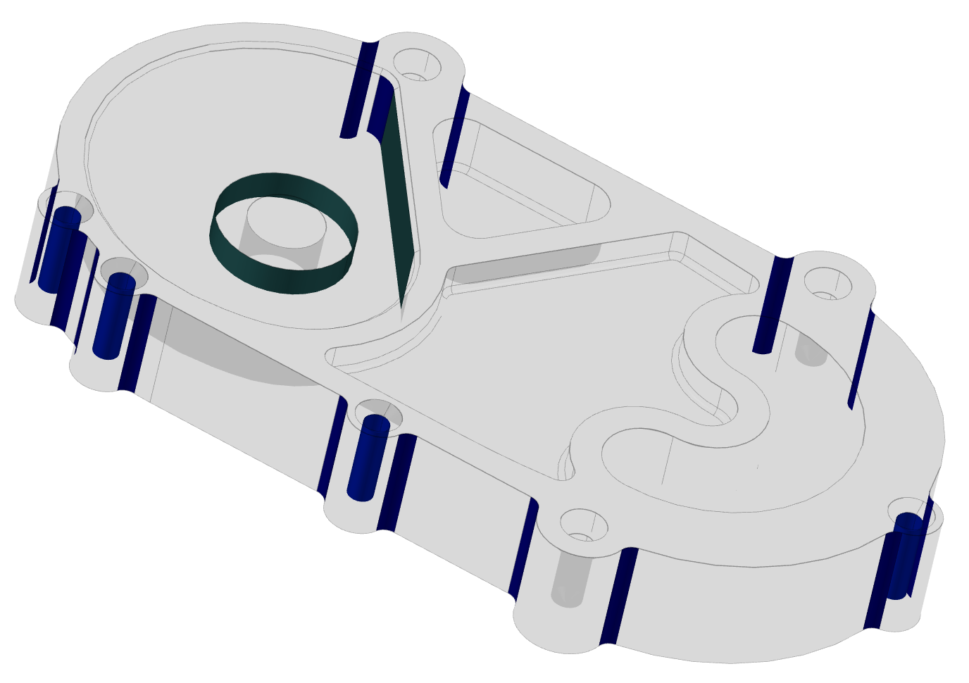
| Model: Fresamento_CAM1_v3.stp
Part #0 ["Fresamento_CAM1"] - solid #0 has:
Deep Hole Issue(s): 4
4 Hole(s) with
expected max depth: 29.841 mm
actual depth: 31.3245 mm
Non Standard Diameter Hole Issue(s): 4
4 Hole(s) with
nearest standard diameter: 9 mm
actual diameter: 8.526 mm
...
Total issues: 24
|
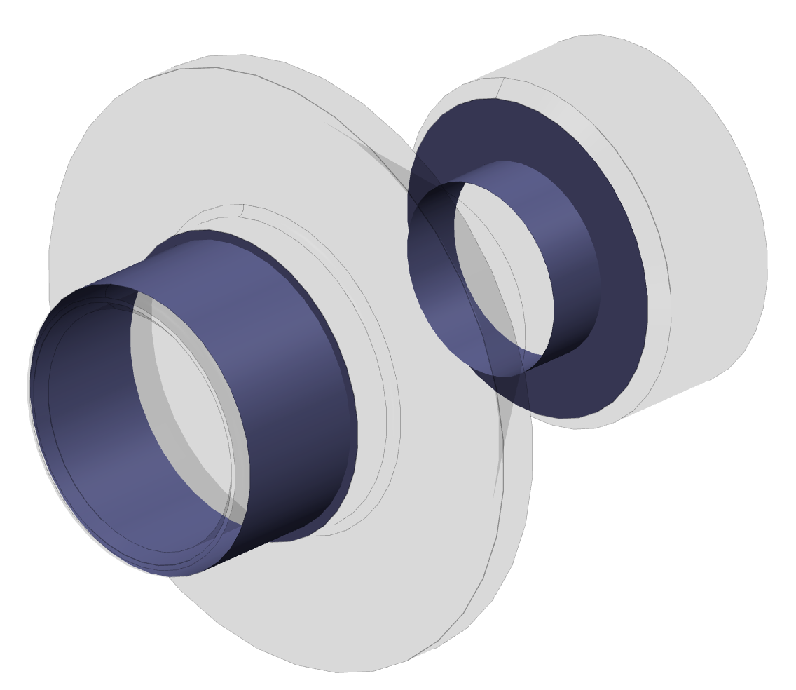
| Model: senthi
Part #0 ["drawing no 1"] - solid #0 has:
Non Standard Radius Milled Part Floor Fillet Issue(s): 2
1 Floor Fillet(s) with
nearest standard radius: 4 mm
actual radius: 5 mm
1 Floor Fillet(s) with
nearest standard radius: 4 mm
actual radius: 50 mm
Non Perpendicular Milled Part Shape Issue(s): 1
1 Shape(s) with
actual angle: 141.936 deg
Milled Part External Edge Fillet Issue(s): 1
Inconsistent Radius Milled Part Floor Fillet Issue(s): 1
1 Floor Fillet(s) with
expected radius: 5 mm
actual radius: 50 mm
Total issues: 5
|