Manufacturing Toolkit

Molding product designs start with CAD files and in order to get the manufacturable molding parts. Those CAD files should follow specific molding design guidelines. Using a Design for Manufacturing (DFM) strategy decreases possible issues in molding design from the beginning, saving both time and money.
The DFM analysis for Molding can be run on a CAD file in order to find any possible design issues, e.g. small rib and bosses draft angles, inconsistent outer diameter, etc. As a result of the analysis, features of the part that don't meet the DFM check criteria will be found.
As the API changes to accommodate the needs of users compatibility will be preserved as much as possible but is ultimately not guaranteed.
The DFM analysis can reveal possible design issues in a molding part, the full list of them is listed here.
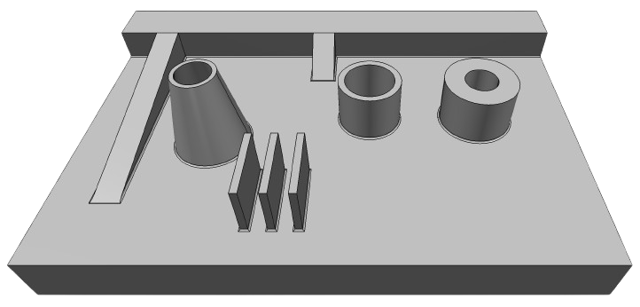
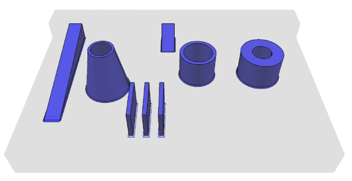
Below is a simple example of DFM analysis.
The DFM analysis can be done on B-Rep representations, namely it works with ModelData::Solid .
DFMMolding_Analyzer is the class that performs molding DFM analysis. It has parameters that allow to modify rules for analysis. There are 2 ways to perform DFM analysis: