Demonstrates how to perform recognition of molding features on a 3D model and print information about found features and their parameters in a console.
Overview
In this example demonstrates how to perform recognition of molding features on a 3D model using molding feature recognition tool (Molding_FeatureRecognizer). For this purpose, used a console application that imports a model, traverses through unique ModelData::Part , creates and runs Molding_FeatureRecognizer, groups and prints information about found features and their parameters into console. Molding feature recognition will be performed for each unique ModelData::Part , but only for the scope of accepted geometries.
Application needs 1 input argument to run:
Usage: molding_feature_recognizer <input_file>, where:
<input_file> is a name of the file to be read
For more information about feature recognition visit Injection Molding page.
Implementation
PartProcessor
class is inherited from SolidProcessor
and overrides ProcessSolid
method that are used to run Molding_FeatureRecognizer on given shapes. Then PrintFeatures
method is used to print information about found features and their parameters in a console.
Visit Model Explore Helper Implementation page for more information about base SolidProcessor
class implementation.
class PartProcessor : public SolidProcessor
{
public:
{
Molding_FeatureRecognizerParameters aRecognizerParameters;
aRecognizerParameters.SetMaxRibThickness (30.0);
aRecognizerParameters.SetMaxRibDraftAngle (0.2);
aRecognizerParameters.SetMaxRibTaperAngle (0.1);
auto aFeatureList = aRecognizer.Perform (theSolid);
PrintFeatures (aFeatureList);
}
};
Defines a topological solid.
Definition Solid.hxx:32
Provides an interface to recognizing molding features.
Definition Molding_FeatureRecognizer.hxx:37
Contains classes, namespaces, enums, types, and global functions related to Manufacturing Toolkit.
Definition LicenseManager_LicenseError.hxx:30
To traverse only unique parts of the imported model, the ModelData::ModelElementUniqueVisitor class is used.
PartProcessor aPartProcessor;
aModel.Accept (aVisitor);
Defines a visitor that visits each unique element only once.
Definition ModelElementVisitor.hxx:87
After performing feature recognition, the object of FeatureGroupManager
class is used to group and sort found molding features. For this purpose, there is a traverse through all found features and add each of them to FeatureGroupManager
with a specified name.
for (size_t i = 0; i < theFeatureList.Size(); i++) {
const auto& aFeature = theFeatureList[i];
aManager.AddFeature ("Screw Boss(es)", "Screw Boss(es)", true, aScrewBoss);
const auto& aBoss =
static_cast<const MTKBase_Boss&
> (aFeature);
aManager.AddFeature ("Boss(es)", "Boss(es)", true, aBoss);
const auto& aRib =
static_cast<const Molding_Rib&
> (aFeature);
aManager.AddFeature ("Rib(s)", "Rib(s)", true, aRib);
}
}
Describes a boss. In CNC Machining a boss is a protrusion or raised area on a workpiece that is creat...
Definition MTKBase_Boss.hxx:31
Describes a rib.
Definition Molding_Rib.hxx:29
Describes a screw boss. In injection molding, the Screw Boss is essentially a cylindrical protrusion ...
Definition Molding_ScrewBoss.hxx:29
After adding all found features to FeatureGroupManager
, a Print
method of the manager is used to print information about found features and their parameters in a console. PrintFeatureParameters
is created to explore and print feature parameters. It uses as an input parameter of Print
method.
{
FeatureGroupManager::PrintFeatureParameter ("outer radius", aScrewBoss.OuterRadius(), "mm");
FeatureGroupManager::PrintFeatureParameter ("inner radius", aScrewBoss.InnerRadius(), "mm");
FeatureGroupManager::PrintFeatureParameter ("draft angle", ToDegrees (aScrewBoss.DraftAngle()), "deg");
const auto& aBoss =
static_cast<const MTKBase_Boss&
> (theFeature);
FeatureGroupManager::PrintFeatureParameter ("length", aBoss.Length(), "mm");
FeatureGroupManager::PrintFeatureParameter ("height", aBoss.Height(), "mm");
FeatureGroupManager::PrintFeatureParameter ("width", aBoss.Width(), "mm");
const auto& aRib =
static_cast<const Molding_Rib&
> (theFeature);
FeatureGroupManager::PrintFeatureParameter ("length", aRib.Length(), "mm");
FeatureGroupManager::PrintFeatureParameter ("height", aRib.Height(), "mm");
FeatureGroupManager::PrintFeatureParameter ("thickness", aRib.Thickness(), "mm");
FeatureGroupManager::PrintFeatureParameter ("draft angle", ToDegrees (aRib.DraftAngle()), "deg");
}
};
aManager.Print ("features", PrintFeatureParameters);
Describes a base class of MTK based features.
Definition MTKBase_Feature.hxx:33
Visit Feature Group Helper Implementation page for more information about FeatureGroupManager
class implementation.
Example output
Below is an example output for model from ./examples/models/Part3.stp
.
Model | Example output |
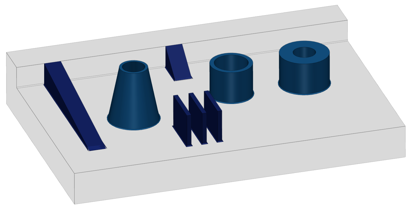
| Model: Part3.stp
Part #0 ["Part3"] - solid #0 has:
Rib(s): 5
1 Rib(s) with
length: 33.2764 mm
height: 15.5984 mm
thickness: 15 mm
draft angle: 0 deg
3 Rib(s) with
length: 40 mm
height: 29 mm
thickness: 3.91237 mm
draft angle: 0 deg
1 Rib(s) with
length: 127.988 mm
height: 18.7895 mm
thickness: 15 mm
draft angle: 0 deg
Screw Boss(es): 3
1 Screw Boss(es) with
outer radius: 18.85 mm
inner radius: 15 mm
draft angle: 0 deg
1 Screw Boss(es) with
outer radius: 22 mm
inner radius: 10 mm
draft angle: 0 deg
1 Screw Boss(es) with
outer radius: 22.3392 mm
inner radius: 20 mm
draft angle: 11.3099 deg
Total features: 8
|
Files