 Manufacturing Toolkit

CNC Machining product designs start with CAD files and in order to get the manufacturable machining parts. Those CAD files should follow specific machining design guidelines. Using a DFM strategy decreases possible issues in machining design from the beginning, saving both time and money.
The DFM analysis for CNC Machining can be run on a CAD file in order to find any possible design issues, e.g. small and deep holes, non-standard radius floor fillet, etc. Features of the part that don't meet the DFM check criteria will be found as the result of the analysis.
As the API changes to accommodate the needs of users compatibility will be preserved as much as possible but is ultimately not guaranteed.
The DFM analysis can reveal possible design issues in a machining part produced in various sub-processes:
CNC milling refers to the machining process of quickly subtracting material from raw stock until the desired shape is achieved. Milling is performed by round cutters (most commonly end mills) which chip away material laterally with shallow depths of cut. When designing your part, keep in mind the types of tools that are commonly available for CNC milling. If you are able to achieve the features and geometry you need with standard tools, you can reduce cost and lead time. Otherwise, the manufacturer will have to spend time and money sourcing or making specialty tools.
The milling issues that can be found are listed here.
Drilling refers to the operation of creating holes in a piece of material. Drilling tools are designed for vertical cutting and have a conical tip, allowing them to plunge deep into a material.
The drilling issues that can be found are listed here.
CNC Turning is a manufacturing process in which bars of material are held in a chuck and rotated while a tool is fed to the piece to remove material to create the desired shape. In turning operation, design the part for easy fixturing and secure holding. Avoid designs that require sharp corners and sharp points in cutting tools because these make the tools more subject to breakage. It is preferable to avoid interrupted cuts, as they tend to shorten tool life.
The turning issues that can be found are listed here.
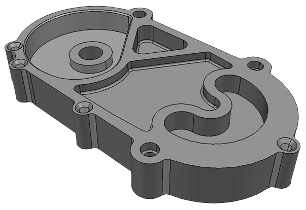
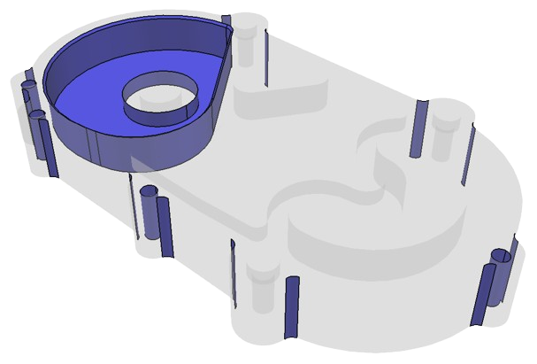
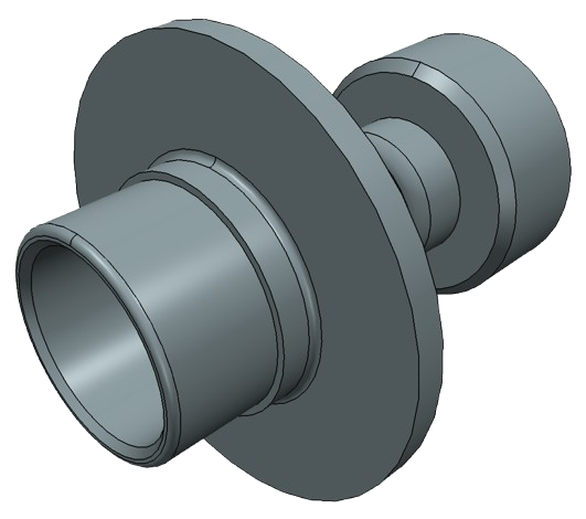
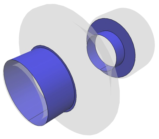
Below are simple examples of DFM analysis.
| 3D model | Issues |
|---|---|
| 
|
| 
|
The DFM analysis can be done on B-Rep representations, namely it accepts ModelData::Solid .
DFMMachining_Analyzer is the class that performs machining DFM analysis. For convenience and flexibility in configuring DFM checks parameters, they are divided by sub-processes: Milling, Drilling, Turning.
There are 2 ways to perform DFM analysis: