| Issue | Description | Example |
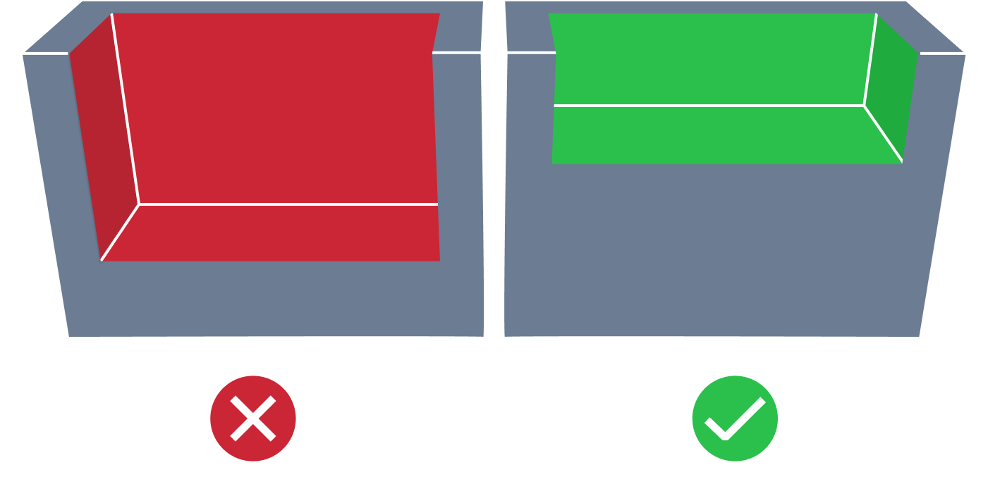
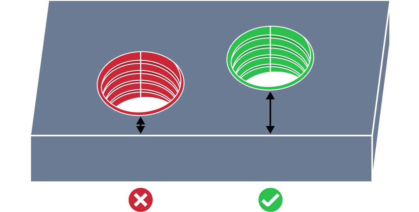
| Deep Pocket | A deep pocket can be problematic in CNC machining milling design due to the difficulty of removing material from the bottom of the pocket. If the pocket is too deep, the cutting tool may not be long enough to reach the bottom, or may deflect excessively, resulting in unacceptable surface finish and accuracy. Additionally, chip evacuation and coolant delivery can be challenging in deep pockets, leading to chip buildup and reduced tool life. |
|
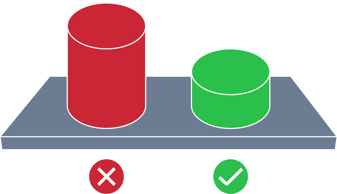
| High Boss | A high boss issue in the milling process refers to a situation where a raised portion (boss) is left on the surface of a workpiece after it has been milled. The presence of a high boss can cause issues with part fitment and assembly, as well as affect the overall aesthetics of the finished product. |
|
| Large Milled Part | Large milled part size can lead to challenges in CNC machining milling design. Workpiece stability can be affected, causing poor surface finish and vibration during the machining process. Tool selection and cutting parameters may need to be adjusted, which can increase machining time and tool wear. Machine capabilities may also be limited, as not all machines can handle large workpieces. |
|
| Small Radius Internal Corner | A small radius internal corner can be problematic in CNC machining milling design due to the difficulty of clearing material from the corner with a cutting tool. Cutting tools have a finite diameter and cannot produce a sharp internal corner, resulting in a small radius. This small radius can create stress points in the workpiece and may not satisfy design requirements for a sharp corner. Additionally, the small radius can be difficult to machine, requiring specialized tooling or techniques to create a high-quality surface finish. |
|
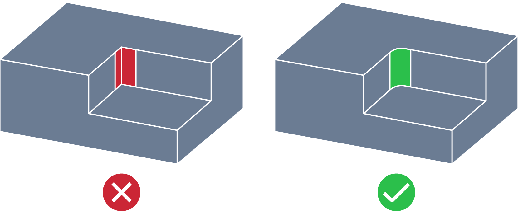
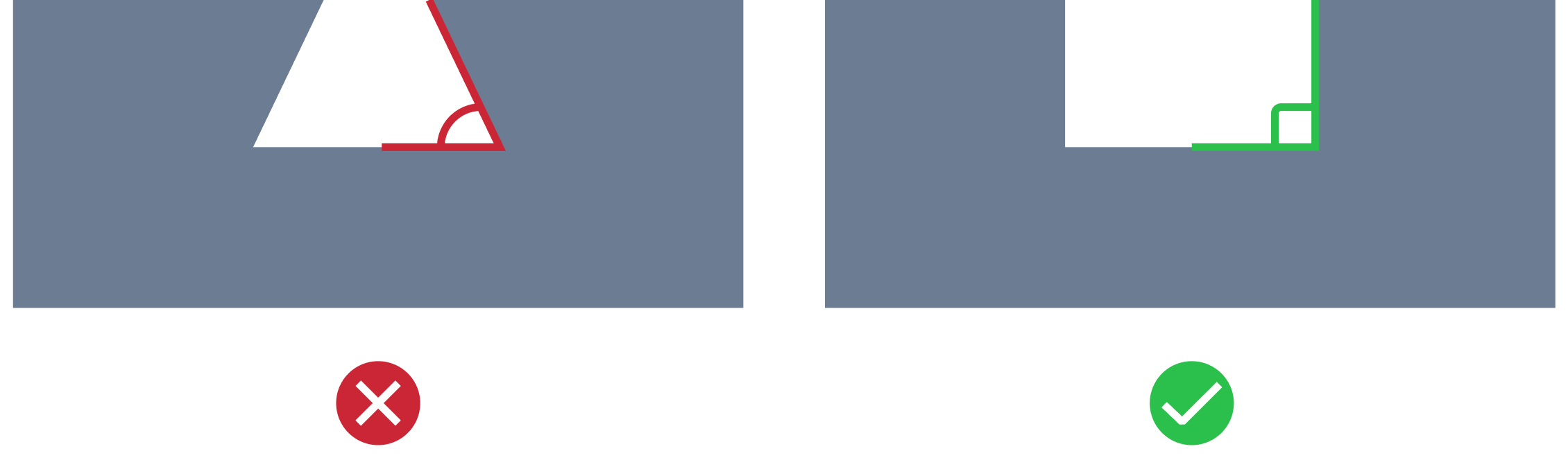
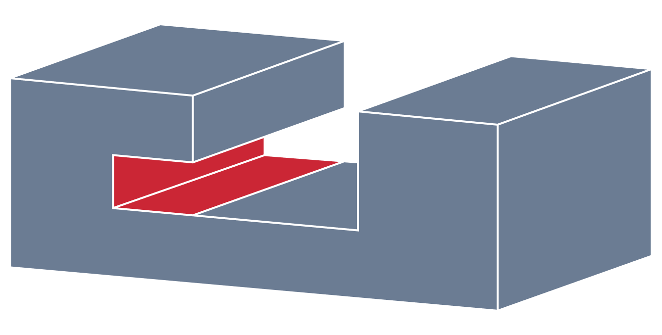
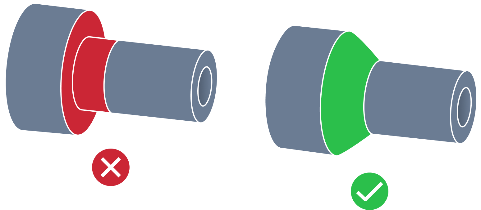
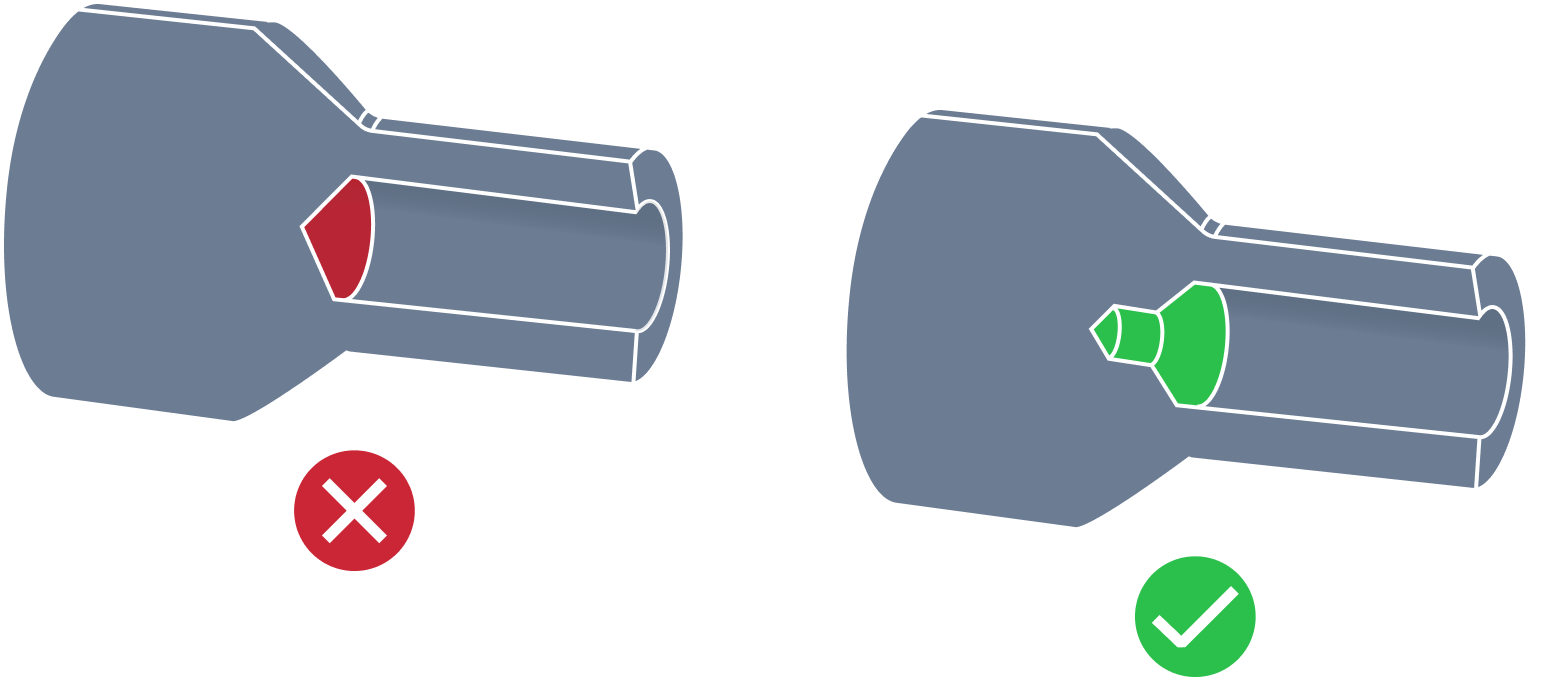
| Non Perpendicular Milled Part Shape | In CNC milling, non perpendicular shape refer to side and bottom surfaces that separated by a floor fillet and are not perpendicular to each other. When surfaces are separated by a floor fillet, the stress concentration increases at that point. When these surfaces are not perpendicular to each other, the stress concentration may be further exacerbated. Moreover, machining two surfaces that are not perpendicular to each other requires positioning the tool at an oblique angle, leading to increased tool wear and reduced tool life. Additionally, the uneven surface requires more machining time and requires specialized tooling and techniques. |
|
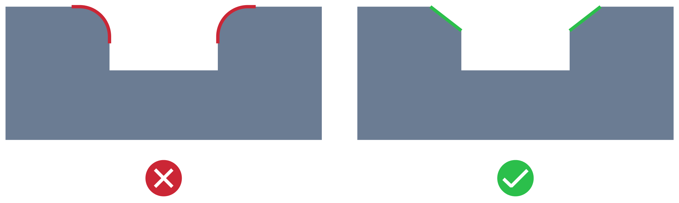
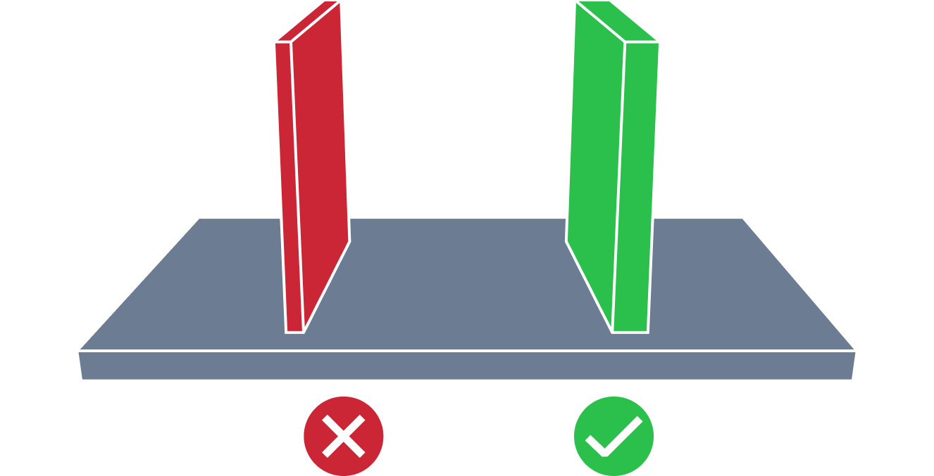
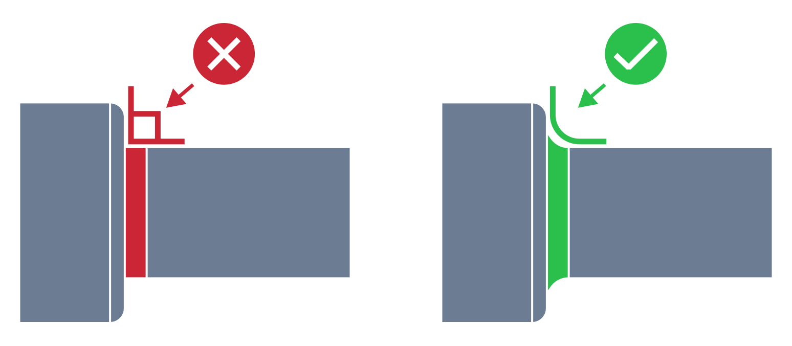
| External Edge Fillet | When designing external edges in CNC machining milling, filleting can pose some issues that need to be considered. Filleting the external edge can potentially lead to stress concentration points due to the bend of the fillet, leading to weak and broken corners. The production of fillets on the external edge also requires special tooling and milling techniques that are expensive compared to other machining methods, e.g. chamfering. Chamfers are preferable compared to fillets on the external edge in CNC machining milling design due to their ability to reduce stress concentrations, provide better clearance, reduce manufacturing costs, and improve overall appearance. |
|
| Non Standard Radius Floor Fillet | A non standard milled part floor radius can be problematic in CNC machining milling design due to the need for special tooling and custom grinding, which can be more expensive and limit the availability of suitable tools. Adjusting cutting parameters can also impact machining time and tool life. Workpiece stability may be compromised due to the added complexity, which can affect surface finish if chatter or vibration occurs. |
|
| Inconsistent Radius Floor Fillet | In CNC milling design, inconsistent floor fillet radii refer to the situation where the size and shape of the fillets on a part are not uniform. Inconsistent radii can weaken the workpiece by creating stress concentration points, causing unexpected failures and compromising the overall strength of the part. Consequently, this can lead to increased manufacturing costs, inefficiencies in the production process, and potential issues during assembly or in use. |
|
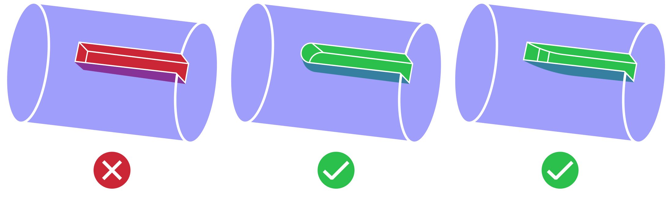
| Narrow Region in Pocket | In CNC machining milling design, a narrow region in a pocket refers to a small or tight area within the pocket that is difficult for the cutting tool to access. Narrow region can pose challenges for the cutting tool in terms of limited visibility, reduced cutting speed, increased tool wear, and potential tool breakage. |
|
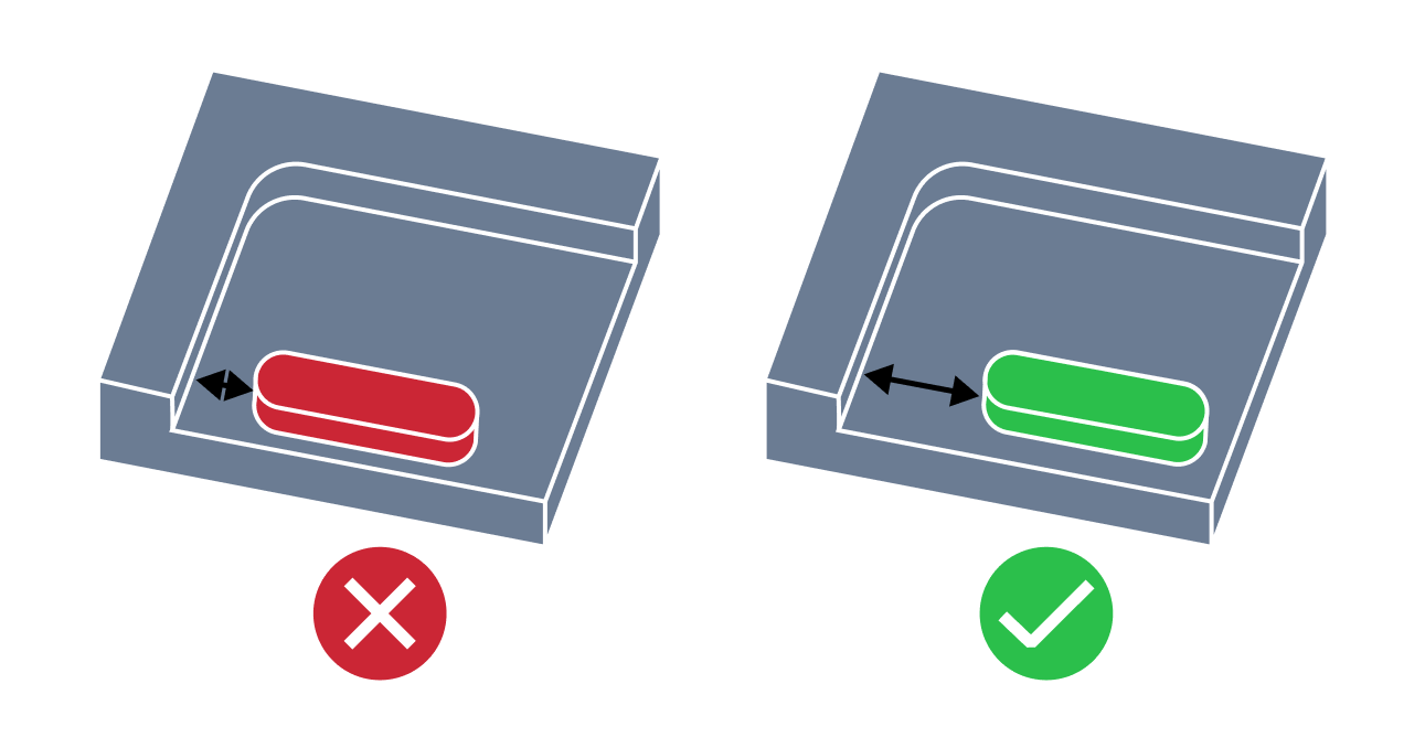
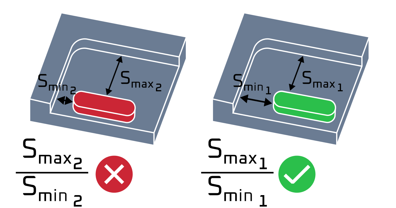
| Large Difference in Regions Size in Pocket | A large difference in region size in a pocket CNC machining milling design can impact the machining process in terms of the required tool selection, appropriate cutting parameters, required material removal, and tool path optimization. |
|
| Small wall thickness | Small wall thickness issue in CNC machining milling design refers to the challenge of machining features with thin walls. This issue arises due to the limitations imposed by the cutting tools, machining parameters, and material properties. When milling thin walls, they are more prone to part distortion and breakage caused by tool vibration. Therefore, it is recommended to maintain wall thicknesses at least 0.8 mm for stability during manufacture. |
|
| Undercut | Undercut issue refers to the case when overhangs create hidden areas that a standard end mill cannot reach because of the limited tool access. These areas can be machined only with specialized tools such as T-slot or lollipop cutters, leading to extra setups, longer cycle times, and higher cost. |
|
| Issue | Description | Example |
| Small Hole Diameter | Small diameter hole issue in CNC machining drilling design refers to the challenge of creating a hole with a diameter smaller than the standard drill bit size. The issue arises due to the limitations of the drill bit size and the possible occurrence of tool wear, deflection, and vibration during the drilling process. When drilling a small diameter hole, tool deflection and vibration become a significant problem and can cause poor hole quality, such as non-circularity, rough edges, and burrs. |
|
| Deep Hole | Drilling deep holes is not a simple task and requires careful consideration of various factors such as drill geometry, coolant supply, chip removal, and machine rigidity. During the drilling process, chips and heat generated from the cutting action accumulate in the hole and can cause tool wear and failure, as well as damage to the workpiece. Another challenge is maintaining the straightness and accuracy of the hole. As the drill penetrates deeper into the workpiece, it may deflect due to the increased cutting forces. |
|
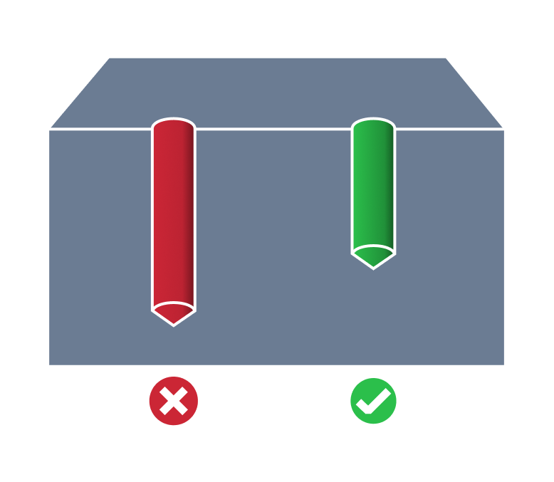
| Flat Bottom Hole | The flat bottom hole issue in CNC machining drilling design refers to the challenge of creating a hole with a perfectly flat bottom surface. Traditional drill bits produce domed or conical-shaped holes with rounded bottom edges, which can be problematic when the application requires a perfectly flat surface. To achieve a flat-bottom hole, specialized drill bits or end mills are used, which can be expensive, but they produce accurate and precise results. |
|
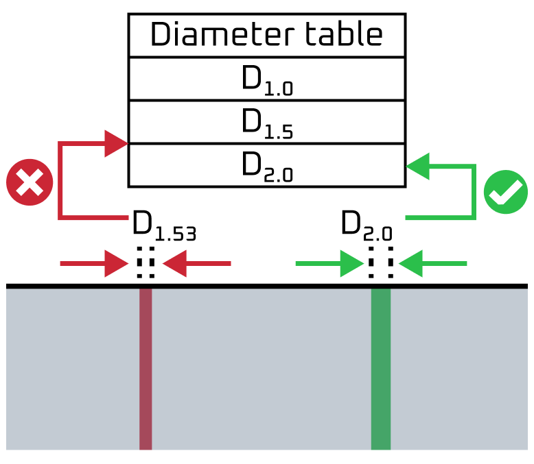
| Non Standard Hole | In CNC machining drilling design, non-standard diameter hole issue refers to the situation where the diameter of the hole required in the design is not a standard size. This can create challenges in the machining process as it may require special tooling or custom programming to achieve the desired hole size. The issue arises because most CNC machines are designed to work with standard drill sizes that are readily available in the market. However, when a design calls for a non-standard size, it can be challenging to find the appropriate tooling or program the machine to achieve the desired result, which can increase the final cost of manufacturing. |
|
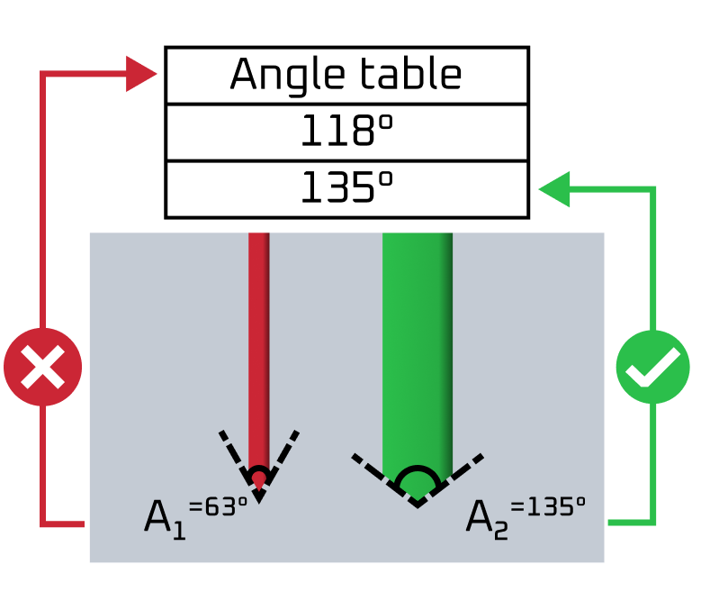
| Non Standard Drill Point Angle | In CNC machining drilling design, non standard drill point angle blind hole issue refers to the situation where the required angle in the design is not a standard size. The standard angle is important for achieving optimal performance and accuracy in drilling operations. A standard angle is commonly used because it provides a good balance between cutting speed and chip clearance, while also minimizing the risk of drill breakage or chipping. |
|
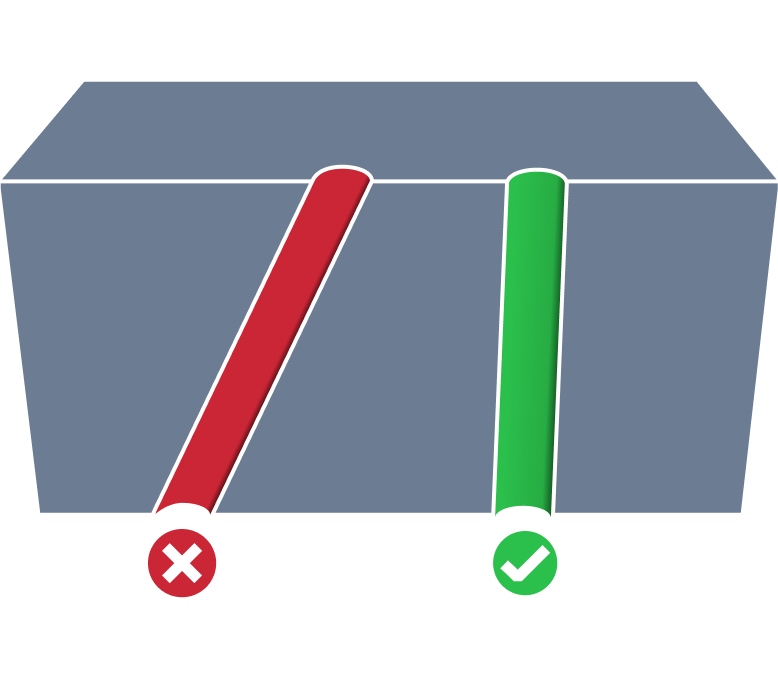
| Non Perpendicular Hole | The non-perpendicular hole issue in CNC machining drilling design occurs when a hole is drilled at an angle that is not exactly 90 degrees to the surface of the workpiece. Non-perpendicular holes can lead to poor fitting, loose connections, and reduced structural strength. |
|
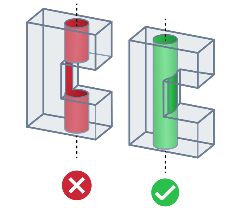
| Intersecting Cavity Hole | In CNC machining, the issue of holes intersecting cavities can arise when designing a part that requires both through-holes and closed cavities. If the cavity intersects with the hole, it can create a number of issues during the drilling process. The drill bit may become trapped in the cavity, or the drill may produce an irregularly-shaped hole that does not pass cleanly through the part. In extreme cases, the drill bit may even break off inside the part, causing damage and requiring costly repairs. It's better to avoid drilling a hole through the cavity or at least maximize the drilled material percent, so that the center line of a hole will be outside the cavity. |
|
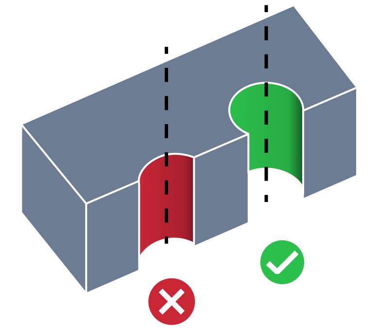
| Partial Hole | Partial hole issue in CNC machining drilling design refers to the difficulty of achieving a complete and uniform hole when drilling close to the edge of a workpiece. Drilling near the edge of a part can create issues such as tool deflection, material deformation, and cracking. Therefore, it's better to avoid partial holes or at least maximize the drilled material percent. |
|
| Small Distance Between Threaded Hole And Edge | In CNC machining, small distance between a threaded hole and the edge of a part refers to the placement of a hole being too close to the part boundary. This issue can cause thread stripping, breakout at the wall, or excessive vibration during tapping. As a result, the hole may require retapping or redesign, which increases machining cost and reduces reliability of the final part. |
|
| Issue | Description | Example |
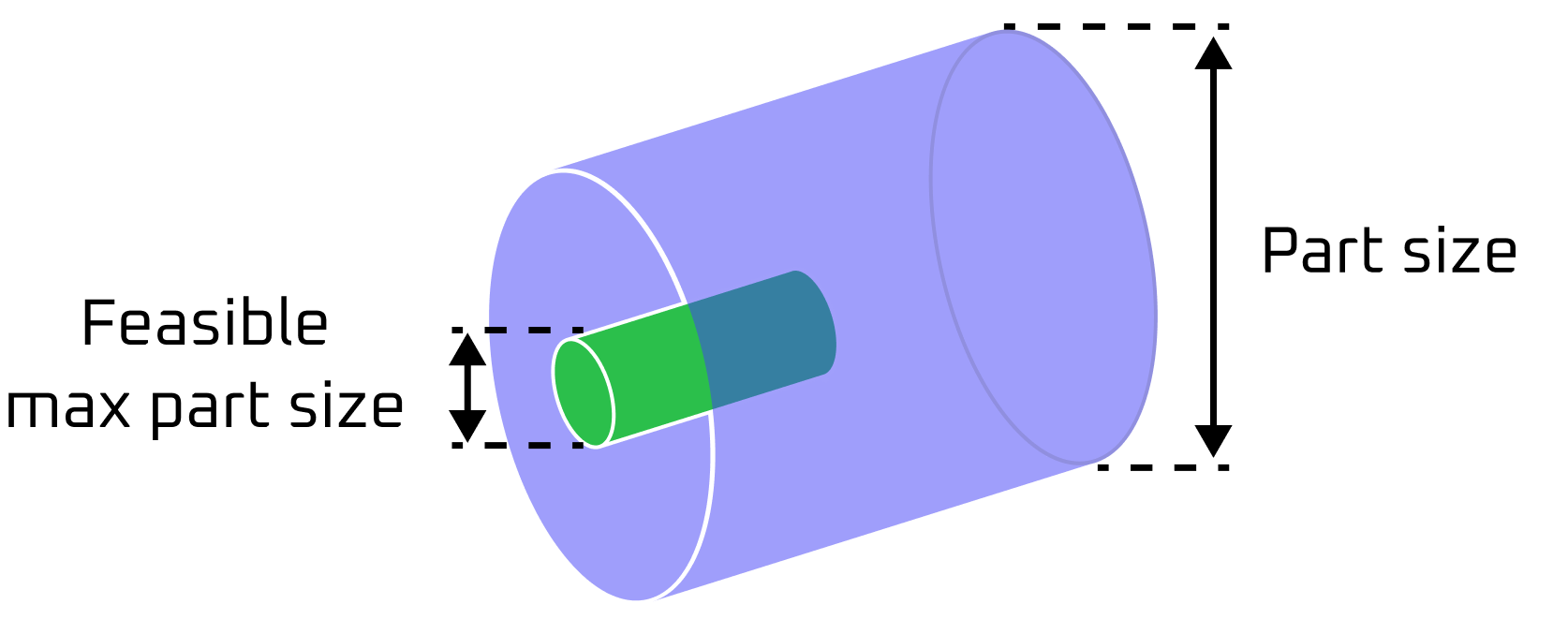
| Deep Bored Hole | Deep bored hole issue in CNC machining turning design refers to the challenge of creating deep and narrow holes in a workpiece using a turning process. The issue arises due to the length-to-diameter ratio of the boring tool, which affects the stability and precision of the process. As the depth of the hole increases, the tool's deflection increases, reducing accuracy and causing tool failure. |
|
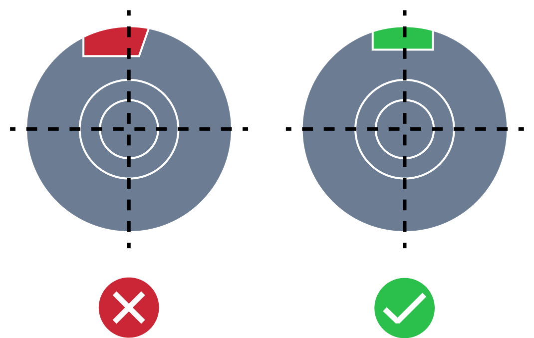
| Irregular Outer Diameter Profile Relief | In CNC machining turning design, a turned part with an irregular outer diameter profile relief issue refers to a part with a non-uniform outer diameter that has a relief or indentation in certain areas. This means that the surface of the part does not have a smooth or uniform contour, and there may be inconsistencies or deviations in the diameter. This can lead to problems with the functionality and performance of the part, as it may not fit properly with other components or may cause friction or wear. |
|
| Large Turned Part | A large turned part issue in CNC machining turning design refers to the difficulties faced in producing oversized components in a turning operation. These parts require specialized equipment and expertise, as well as careful consideration of factors such as stability, tool selection, and programming. Some common challenges include maintaining consistency of material removal, ensuring proper chip evacuation, and minimizing vibration and deflection. |
|
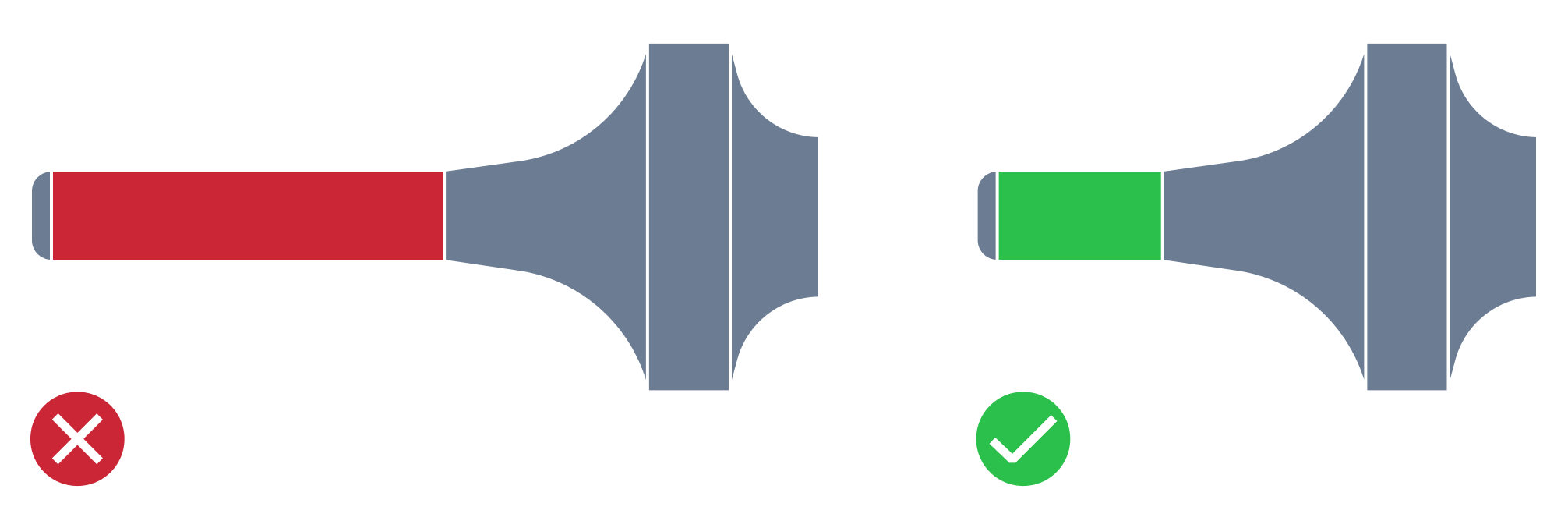
| Long-Slender Turned Part | The long-slender turned part issue in CNC machining turning design refers to the difficulty in producing a thin and elongated component with high precision and accuracy. This type of part may be prone to deflection, vibration, and chatter during the machining process, which can lead to surface finish defects, dimensional inaccuracies, and even part failure. |
|
| Small Depth Blind Bored Hole Relief | In CNC machining, a blind bored hole is a hole that does not go through the entire workpiece, i.e., it has a bottom. The relief depth of the blind bored hole refers to the clearance required for the tool used to drill the hole to operate effectively without getting damaged or breaking. The issue of small relief depth occurs when the space available for drilling is limited, or the tool has a limited depth of cut, which restricts the depth of the hole that can be drilled. This can cause quality issues in the machined part, as the desired hole depth will not be achieved, leading to inaccuracies in the finished product. |
|
| Small Radius Internal Corner | A turned part with a small internal corner radius issue in CNC machining turning design can cause problems during the machining process, as the tool used to cut the part may not be able to reach into the tight radius, resulting in an unfinished surface. The issue may also result in structural weakness, as sharp internal corners can create stress points that may compromise the integrity of the part. |
|
| Square End Keyway | A square keyway is a slot that mechanical components can be attached to. Creating a square keyway when designing a part for CNC machining turning presents some difficulties. One of these issues is the precise accuracy and size of the keyway slot. The dimensions and tolerances of the keyway must be within specific parameters for the mechanical component to be secured properly onto the shaft. Secondly, the corners of the square keyway can be prone to damage, including stress concentrations that can lead to weakness and eventual failure. |
|
| Non Symmetrical Axial Slot | An axial slot is a pocket on a turning face to which mechanical components can be attached to. When designing a part for CNC machining turning it's necessary to take into account possible problems of coupling with other parts. For instance, one of them is wrong part alignment which can be a result of asymmetrical about turn-axis width of the slots. |
|
 Manufacturing Toolkit