Demonstrates how to perform molding design analysis on a 3D model and print information about found issues and their parameters in a console.
Overview
This example demonstrates how to perform molding design analysis on a 3D model using molding DFM analyzer tool (DFMMolding_Analyzer). For this purpose, used a console application that imports a model, traverses through unique ModelData::Part , creates and runs DFMMolding_Analyzer, groups and prints information about found issues and their parameters into console. Molding design analysis will be performed for each unique ModelData::Part , but only for the scope of accepted geometries.
Application needs 1 input argument to run:
Usage: molding_dfm_analyzer <input_file>, where:
<input_file> is a name of the file to be read
For more information about molding design analysis visit Injection Molding Design for Manufacturing (DFM) page.
Implementation
PartProcessor class is inherited from SolidProcessor and overrides ProcessSolid method that are used to run design analysis on given shape.
Visit Model Explore Helper Implementation page for more information about base SolidProcessor class implementation.
class PartProcessor : public SolidProcessor
{
public:
{
auto anIssueList = aDFMAnalyzer.Perform (aData);
PrintIssues (anIssueList);
}
};
Provides an interface to run DFM Molding analysis.
Definition DFMMolding_Analyzer.hxx:39
Defines parameters used in injection molding design analysis.
Definition DFMMolding_AnalyzerParameters.hxx:34
Defines a topological solid.
Definition ModelData/Solid.hxx:30
Provides an interface to run several analyzer tools for different types of Molding processing.
Definition Molding_Analyzer.hxx:40
Molding_Data Perform(const ModelData::Solid &theSolid, const ProgressStatus &theProgressStatus=ProgressStatus())
Runs the analyzing process.
Definition Molding_Analyzer.cxx:79
void AddTool(const Molding_AnalyzerTool &theTool)
Adds additional tool to run during analyzing process.
Definition Molding_Analyzer.cxx:99
Defines data used in Molding analysis.
Definition Molding_Data.hxx:34
Provides an interface to recognizing molding features.
Definition Molding_FeatureRecognizer.hxx:36
Defines parameters used by Molding_FeatureRecognizer.
Definition Molding_FeatureRecognizerParameters.hxx:32
void SetMaxRibDraftAngle(double theDraftAngle)
Sets maximum draft angle along height of rib in radians.
Definition Molding_FeatureRecognizerParameters.cxx:76
void SetMaxRibThickness(double theThickness)
Sets maximum thickness at top of rib in radians.
Definition Molding_FeatureRecognizerParameters.cxx:99
void SetMaxRibTaperAngle(double theTaperAngle)
Sets maximum taper angle along length of rib in radians.
Definition Molding_FeatureRecognizerParameters.cxx:53
Contains classes, namespaces, enums, types, and global functions related to Manufacturing Toolkit.
Definition LicenseError.hxx:27
To traverse only unique parts of the imported model, the ModelData::ModelElementUniqueVisitor class is used.
PartProcessor aPartProcessor;
aModel.Accept (aVisitor);
Defines a visitor that visits each unique element only once.
Definition ModelElementVisitor.hxx:90
After performing design analysis, the object of FeatureGroupManager class is used to group and sort found issues. For this purpose, there is a traverse through all found issues and add each of them to FeatureGroupManager with a specified name.
for (size_t i = 0; i < theIssueList.Size(); ++i) {
const auto& anIssue = theIssueList[i];
aManager.AddFeature ("Irregular Core Depth Screw Boss Issue(s)", "Screw Boss(es)", true, anIssue);
aManager.AddFeature ("Irregular Core Diameter Screw Boss Issue(s)", "Screw Boss(es)", true, anIssue);
} else ...
}
Describes irregular core depth screw boss issues found during injection molding design analysis.
Definition DFMMolding_IrregularCoreDepthScrewBossIssue.hxx:33
Describes irregular screw boss core diameter issues found during injection molding design analysis.
Definition DFMMolding_IrregularCoreDiameterScrewBossIssue.hxx:33
After adding all found issues to FeatureGroupManager, a Print method of the manager is used to print information about found issues and their parameters in a console. PrintFeatureParameters is created to explore and print issue parameters. It uses as an input parameter of Print method.
{
FeatureGroupManager::PrintFeatureParameter ("actual height", aICDSBIssue.ActualHeight(), "mm");
FeatureGroupManager::PrintFeatureParameter ("actual core depth", aICDSBIssue.ActualCoreDepth(), "mm");
FeatureGroupManager::PrintFeatureParameter ("expected min core diameter", aICDSBIssue.ExpectedMinCoreDiameter(), "mm");
FeatureGroupManager::PrintFeatureParameter ("expected max core diameter", aICDSBIssue.ExpectedMaxCoreDiameter(), "mm");
FeatureGroupManager::PrintFeatureParameter ("actual core diameter", aICDSBIssue.ActualCoreDiameter(), "mm");
} else if ...
};
aManager.Print ("issues", PrintFeatureParameters);
Describes a base class of MTK based features.
Definition MTKBase_Feature.hxx:32
Visit Feature Group Helper Implementation page for more information about FeatureGroupManager class implementation.
Example output
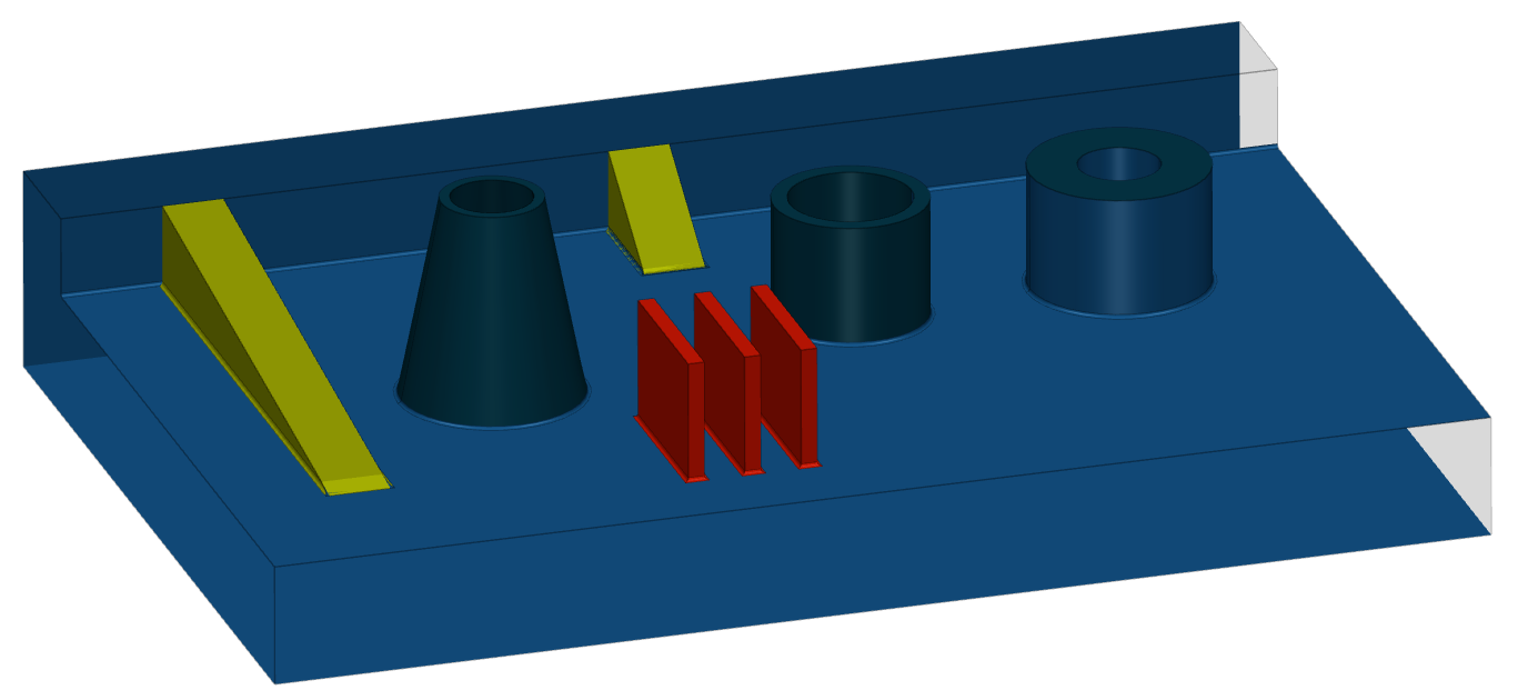
Below is an example output for model from ./examples/models/Part3.stp.
| Model | Example output |
|
| Model: Part3
Part #0 ["Part3"] - solid #0 has:
High Rib Issue(s): 3
3 Rib(s) with
expected max height: 11.7371 mm
actual height: 29 mm
High Screw Boss Issue(s): 3
1 Screw Boss(es) with
expected max height: 3.50883 mm
actual height: 50 mm
1 Screw Boss(es) with
expected max height: 5.775 mm
actual height: 30 mm
1 Screw Boss(es) with
expected max height: 18 mm
actual height: 30 mm
...
Total issues: 84
|
Files
 Manufacturing Toolkit