Manufacturing Toolkit

Manufacturing Toolkit (MTK) is a set of APIs that allows to analyze 3D models, retrieve manufacturing process specific information, identify and collect features (geometric modifications that have been made on the workpiece) and find various possible design issues. The results of the analysis can be used later with other tools to estimate manufacturing costs.
MTK is written in C++ and provides wrappers for C# , Java and Python . This documentation is generated from the original C++ code, and that is why uses C++ API conventions. Nonetheless, understanding MTK API for other languages should be very straightforward, especially if consulting numerous examples.
See also:
MTK allows to recognize machining features produced by CNC Machining processes (Milling/Drilling/Turning), such as: holes of various types (through, blind, flat-bottom, partial), countersinks, pockets, etc (the full list of features is listed here). Below is a simple recognition example.
| |
| 3D model | Features |
To recognize machining features, simply run Machining_FeatureRecognizer on a solid part, as shown below. A list of found features will be returned as the result of recognition.
The tool has parameters that affect the result. In order to set them, just add the following lines:
See also:
CNC Machining product designs start with CAD files and in order to get the manufacturable machining parts. Those CAD files should follow specific machining design guidelines. A Design for Manufacturing (DFM) analysis for CNC Machining can be run on a CAD file in order to find any possible design issues, e.g. small and deep holes, non-standard radius floor fillet, etc. As a result of the analysis, features of the part that don't meet the DFM check criteria will be found.
| |
| 3D model | Issues |
See also:
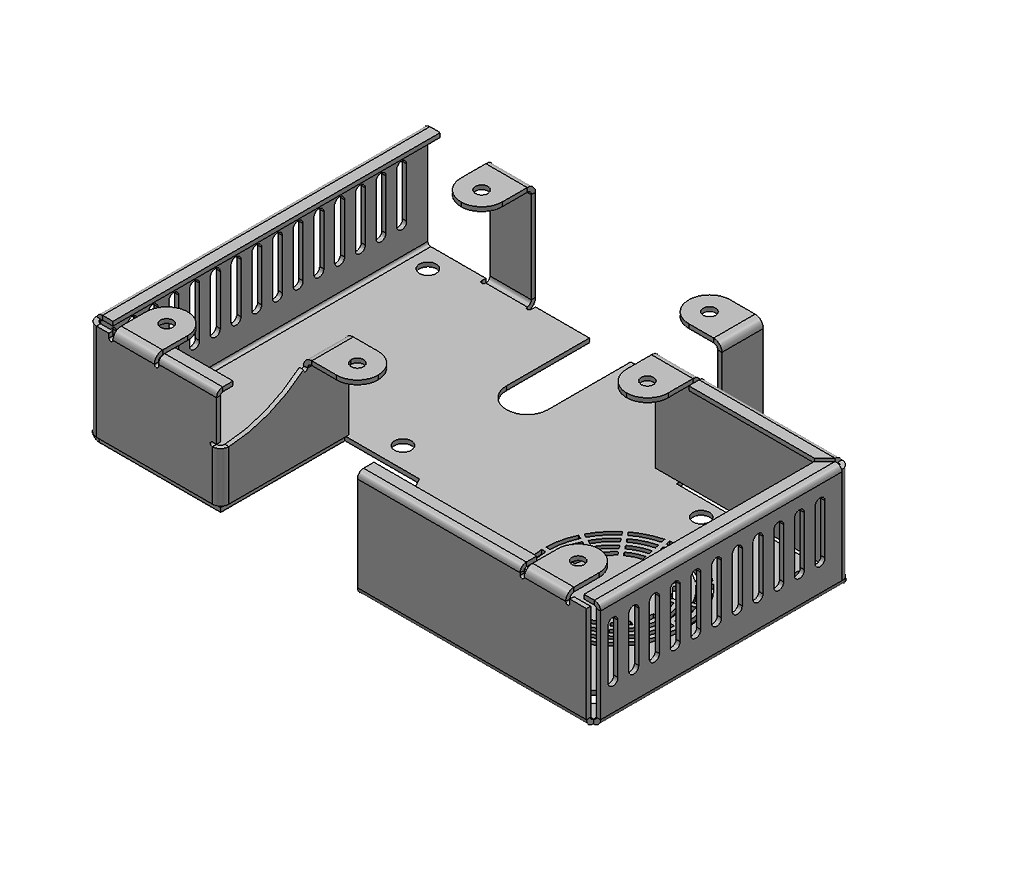
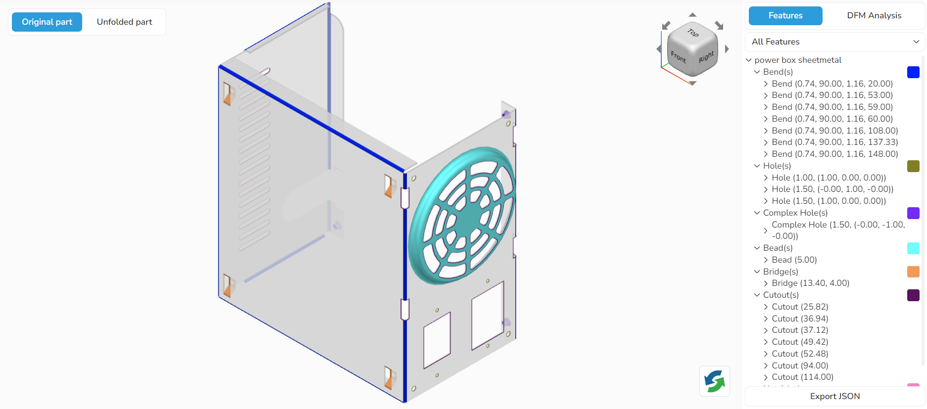
MTK allows to recognize sheet metal features, such as: bends, beads, holes, cutouts, etc (the full list of features is listed here). Below is a simple recognition example.
|
|
| 3D Model | Features |
To start feature recognition of sheet metal part, simply run SheetMetal_FeatureRecognizer on a part, as shown below. A list of found features will be returned as the result of recognition.
See also:
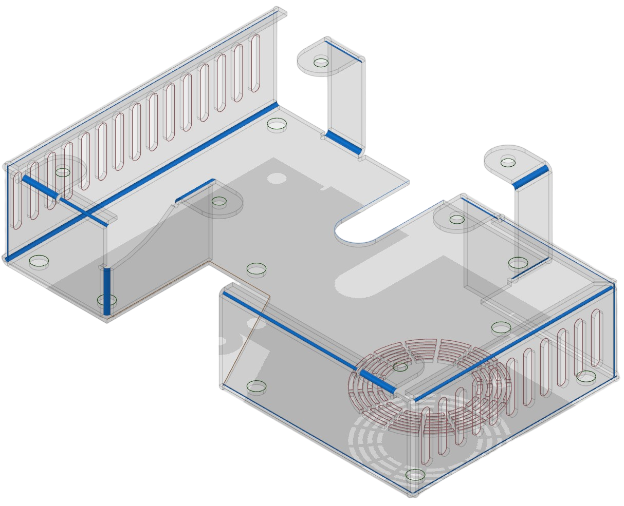
Sheet metal design guidelines are followed to ensure the final product is precise and to reduce costs. Unfortunately, some engineers of sheet metal enclosures and parts do not design with the manufacturing process in mind. This gives manufacturers a hard time fixing errors that could have been avoided in the design stage. For this purpose a Design for Manufacturing (DFM) analysis for Sheet Metal can be run on a CAD file in order to find any possible design issues, e.g. small distance between holes, inconsistent bend radii, etc. As a result of the analysis, features of the part that don't meet the DFM check criteria will be found.
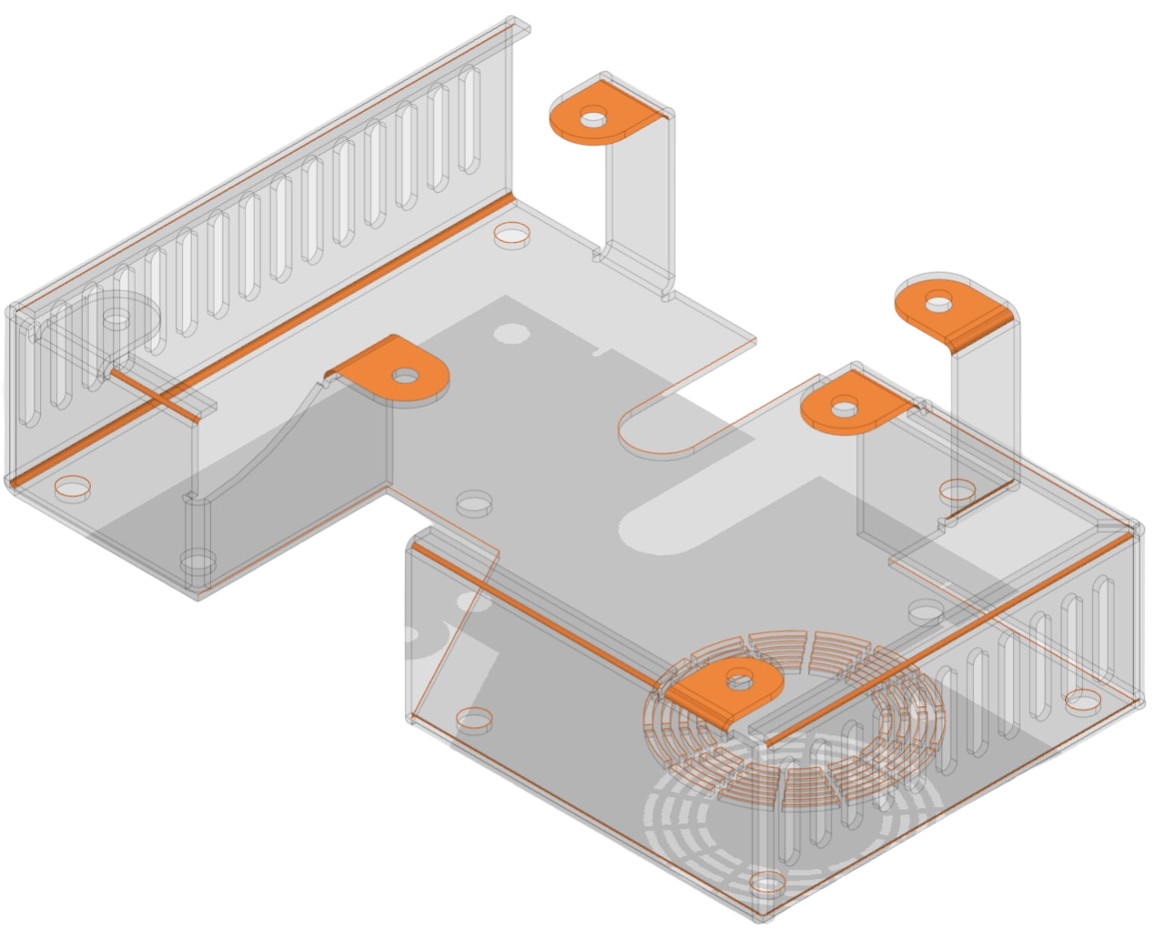
| |
| 3D model | Issues |
See also:
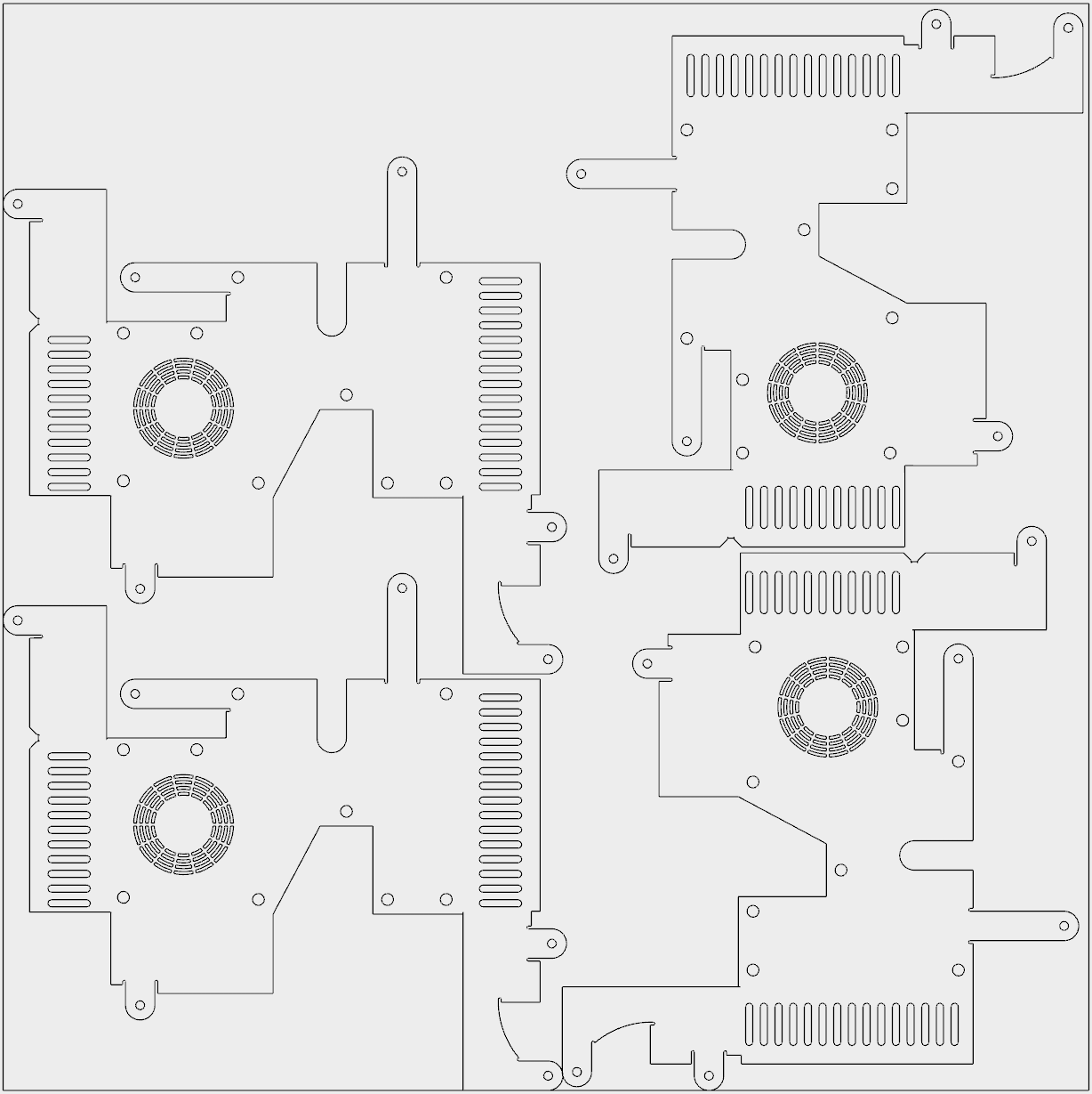
In some scenarios it can be useful to unfold a sheet metal part to get the original flat metal sheet which was used to produce this part, for example:
The following pictures illustrate a sheet metal model and its unfolded view.
3D Model | 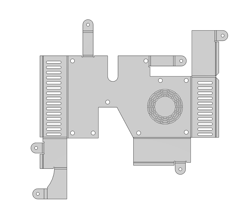
Unfolded View |
To get an unfolding of sheet metal part, simply run SheetMetal_Unfolder on a part, as shown below.
If a part needs to be processed by SheetMetal_FeatureRecognizer and SheetMetal_Unfolder, you can reduce computation time by running the tools as part of the SheetMetal_Analyzer.Perform(), as shown below.
See also:
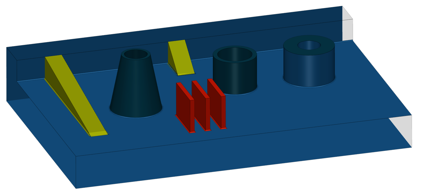
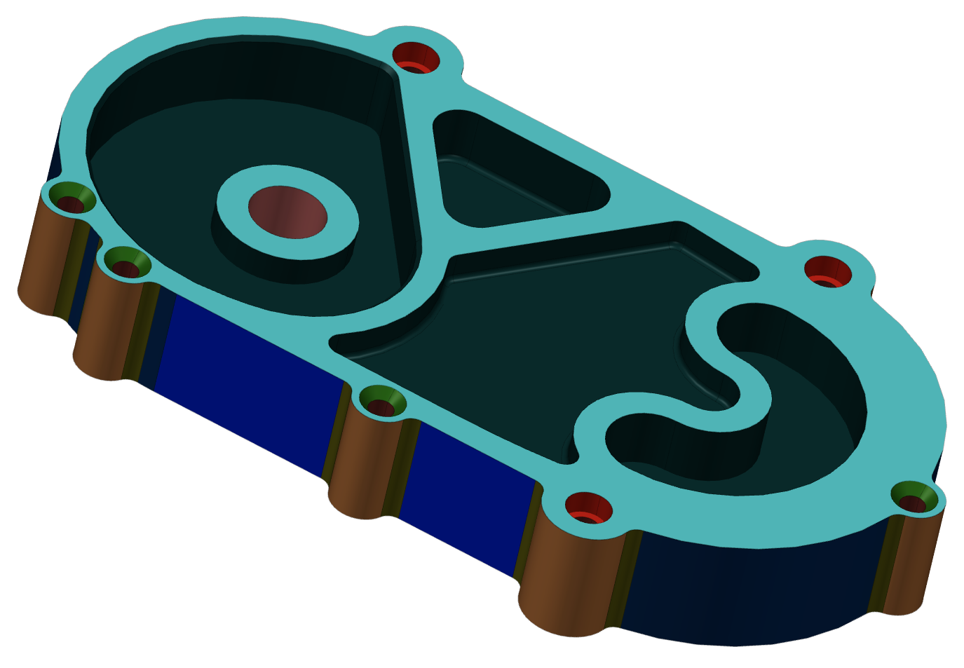
MTK allows to recognize molding features, such as: ribs, screw bosses, etc (the full list of features is listed here). Below is a simple recognition example.
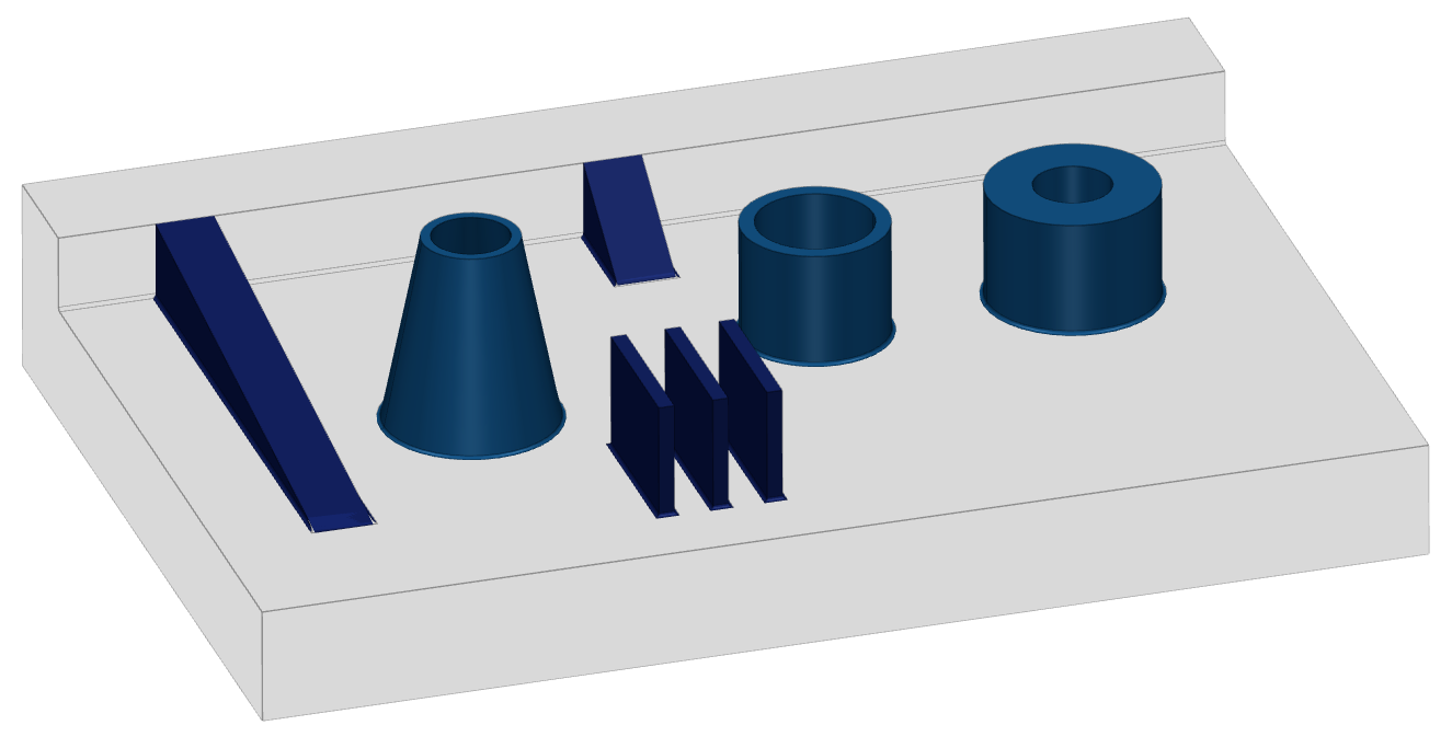
|
|
| 3D Model | Features |
To recognize molding features, simply run Molding_FeatureRecognizer on a solid part, as shown below. A list of found features will be returned as the result of recognition.
See also:
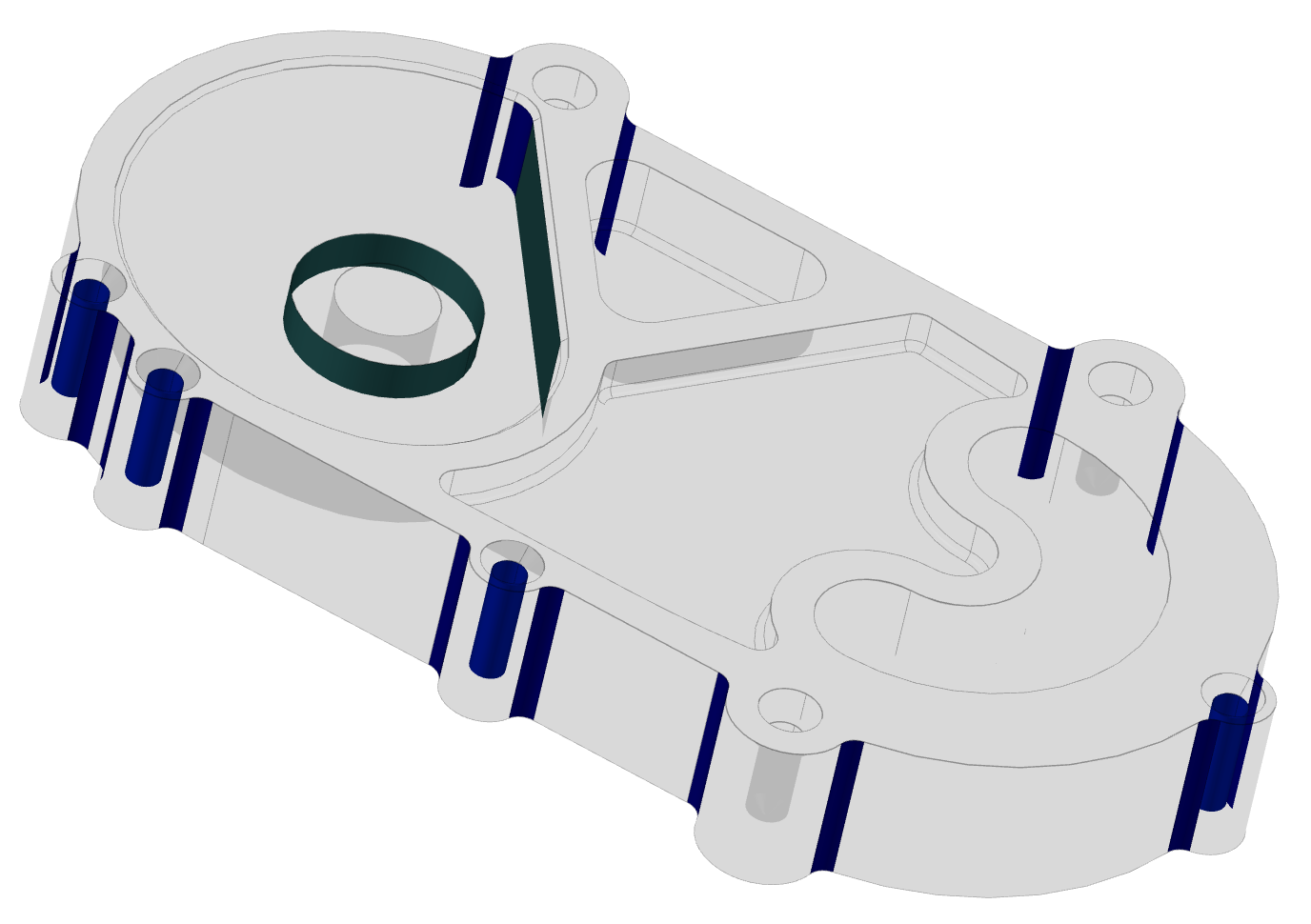
Molding designs require meticulous attention to detail to ensure successful manufacturing process. A Design for Manufacturing (DFM) analysis for Molding can be run on a CAD file in order to find any possible design issues, e.g. small draft angles, irregular diameters and heights for ribs and screw bosses, etc. As a result of the analysis, features of the part that don't meet the DFM check criteria will be found.
See also:
The nesting algorithm enables optimal arrangement of 2D patterns on flat materials (e.g., sheet metal, wood, plastic) to minimize waste. The process uses a genetic algorithm to explore and select the most efficient layouts. Only 2D drawings without bend lines are supported. To run nesting, create a Nesting_Computer, set parameters, define materials, and add patterns. The result is Nesting_Data, which can be converted into a drawing. For more details refer to Nesting Process.
The image below shows a possible result generated with the defult configurations:
See also:
With the help of Manufacturing Toolkit Web (MTK Web) you can build a responsive MaaS (Manufacturing-as-a-Service) solution that will visualize and process 3D CAD files in web apps.
|
You can use MTK Converter Example to prepare your data for web visualization.
MTK contains base algorithms for measurements computing:
MTK contains advanced algorithms for measurements computing: